So I have a 3D Laser Scanner – now what?

There is a common misconception that 3D laser scanning is a one-size-fits-all solution for every project. The truth is, this new technology is powerful – but it’s not for every surveying firm and it’s not a fit for every project.

First, surveying with a scanner is not the same as with a total station or GPS. For one, there are no field notes – just lots of data points and photographic files.

Another important distinction is the line of site requirement. When a survey crew sets up a survey instrument, they are typically looking for a line of site to the next point. That’s not the case with a scanner, which requires a more focused coverage. Some setups may only be 15 feet from the last if you need to get more views of a complicated structure.

With laser scanning, it is common to gather data that the client does not need at the time, but may need to use later. Once a site is scanned and post-processed, engineers and analysts can check and re-check engineering quality data on a desktop computer any time.

Computer power plays a significant role in successful laser scanning. The post-processing of laser scanned data is critical and can be tedious on older computers. Before buying into scanning technology, invest in at least 64-bit machines with fast graphics cards and as much RAM memory as possible.

You may want one computer to process the scan data and another to process the photographic data. Laser scanners create enormous files that must be managed carefully in a consistent workflow. (Our exterior projects normally have 1 to 10 gigabytes of data and a major industrial facility can have over 150 gigabytes of data.) Create to processes and work flows to store and back up everything.

Finally, don’t expect clients to beat down your door, demanding a 3D laser scan. Buying a scanner won’t make jobs magically appear. The market is just learning about this technology and though it is well worth the investment for those firms willing to do the legwork to find the clients who want and need its special capabilities, you will have to do a lot of educating and demonstrations of what the world of 3D can bring to clients.

The key is listening to your clients and understanding their needs. Keep in mind that many potential clients don’t know what questions to ask. Until laser scanning becomes as common as GPS, surveyors will have to educate owners, architects, engineers and contractors about the benefits.

###

Tate Jones has over 40 years of experience in land and aerial surveying and was one of the country’s earliest adopters of 3D laser scanning technology. A nationally recognized expert in the field of 3D data capture, he has worked with hundreds of clients in the engineering, architectural and construction industries. Contact him at tjones@lasurveying.com. To learn more about 3D laser surveys, visit www.3DLaserSurveys.com.

Tripod Mounted or Mobile 3D Laser Scanning: Which is the right one for the job?

Riegl Scanner Mounted On Automobile

Riegl Scanner Mounted On Automobile

Leica C10 Terrestrial Scanner

Leica C10 Terrestrial Scanner

Having worked many years with terrestrial lidar platforms, I have had the unique experience of watching the industry grow and expand.  I have attended Leica conferences and Spar conferences in Texas and California every year since 2005 and I have been very impressed with seeing the innovations in 3D Laser data collection platforms. In this article I have purposely decided not to discuss the airborne platforms of fixed wing and helicopter, I will save that for another time. I have spent a lot of time with the tripod based Leica Scanning systems of the last 6 years.  At the same time, at the Spar conference and other equipment shows I also studied the Trimble, Faro and Riegl products as well as others that are excellent systems.  The point of this article is to compare the conditions and cost analysis of using a fixed tripod base 3D Laser Scanning system compared to a mobile truck or automobile mounted system for scanning road way corridors in database preparation for Federal, State, and County transportation projects.

General Project Specifications

While specs change from state to state these are the key factors:  Typically the engineer will request a corridor that is 200’ wide, centered on the existing roadway.  Sometimes it is wider and sometimes narrower.  The spec for vertical accuracy is normally about .10 foot or less accuracy on “hard” pavement and concrete surfaces including the paved shoulder.  All other surfaces in the corridor have to be within 6” vertical accuracy including bare ground, grass, overgrowth and thick vegetation.  Horizontal accuracy is standard second order.  Within the corridor you are expected to pick up all man made features- water valves, power poles, fire hydrants, pavement striping etc. In addition to this, the specifications you are required to have are a second order control point every 3000’ (sometimes closer), and a project control point every 1000’.  So this is the scope we are working toward for comparison of the two 3D Systems.

Comparison and Capabilities

The first thing to remember is that Laser Scanning is very precise on hard surfaces like pavement, houses, and power poles and not very good in vegetation.  I know that many software packages are offering “ bare ground” programs and in a commercial areas, with sparse vegetation that may be relevant but the test we have run using Lidar in foliage showed that the results consistently did not meet the spec of 6” vertical accuracy of the true ground when compared to standard 2nd order topographic survey methods.  So the value of the laser is on the pavement not with the foliage with either system.

The second consideration is that the cost of a tripod mounted 3D laser scanning system is in the $100,000 range, with software, probably $120,000 and can go as high as  $180,000.  A good mobile system with an Inertial Measurement Unit, GPS, two precise laser scanners, video cameras and a mobile computer controller system that allows the data to be captured at 40 or 50 miles per hour can cost between $500,000 and $1,200,000. The best mobile systems are $2,000,000 or more.  This is one of the biggest differences in the systems. So the billable charge per day is more for the more expensive system.

Daily Production Rates

Both systems require fixed survey control points to achieve the most accuracy.  However the effort to put the control in place is the same for both systems.  So while that is a very important factor, it is not a determining factor on which system to use.  The production rate of the systems is vastly different. Using a tripod mounted system for scanning and a two man crew, you can scan 3000 to 4000 feet of high quality data per day depending on density and congestion.  Billing a scanning crew at $3000 per day for data collection and adding another $1000 per day for data registration and feature extraction the cost comes to about $4000 so say it is $1.00 per foot.

Example of Mobile Laser Scan Data

Example of Mobile Laser Scan Data

A mobile vehicle mounted system on the other hand can scan more than 50 miles of roadway per day. That is an enormous difference.   But this system  has the same limiting factors as the tripod system of being less effective in heavily congested areas. It is standard procedure on mobile scanning projects to run the travel lanes multiple times to get the best results.  So the production rate per day of the Mobile is 10 times (or more) greater than the tripod mounted system.

So on the face of it the mobile system sounds better, faster, and most efficient.  That is not always the case.  On real projects where we have compared systems to systems the cost for less than 10 miles of roadway is the same or a little less for the tripod mounted systems and the time frames is about the same for the completed deliverable.  Above 10 miles our experience has shown us that the mobile vehicle mounted system is probably more cost efficient.  Why? The mobilization cost of getting a Mobile system on site. Much like an aerial lidar job, sometimes the biggest cost is getting the aircraft over the site.  The same is true for mobile mapping.  The cost to get a mobile unite on your job can be $5000, or more, for the first mile.  The other factor is that it cost more to process the mobile data as you need to analyze and the various systems and make sure that the GPS and satellites are all working and collecting correctly.  Generally some type of test run is recommended.    I recently priced a job both ways and if you included all the variables 6 miles of road way came in at just under $30,000 and with mobile the cost was closer to $40,000 and I had some prices over $50,000.

There are still two other factors to consider.  As a surveyor I don’t get many transportation projects that are over 8 or 10 miles.  It is just that most projects, because of construction cost and size and cost generally stop at less than 10 miles.  There are exceptions, like long paving jobs that go 40 or 80 miles but they may or may not require highly detail surveys.

Bridge Interchange Project by LandAir Surveying

Bridge Interchange Project by LandAir Surveying

The other factor is speed.  If speed is important because of urgency to a project or danger there are many application where the data should be collected with a mobile unit.  Two examples;  First a 10,000’ runway project on a busy airport.  Normally the client will not allow you to close that type of runway for long periods of time for any reason. So for situations like this typically a mobile system is preferred.   Another example is a very complicated area where there is a necessity for a very fast turnaround of the data.  Some fast track projects require asbuilts data before the next phase of a project can be started.  In these cases mobile scanning has some advantages and the difference in cost maybe worth the savings in time.

Conclusion: Both systems can get good survey grade data if they are used by experienced technicians that understand what they need to be successful.  On actual projects I have priced, projects less than 8 or 10 miles are more cost effective with Tripod mounted systems and projects longer than this are faster and usually less expensive with the Vehicle mounted systems.  One last note! It is important to remember that collecting the hard pavement surfaces is only about 20% to 25% of a normal transportation job.


H. Tate Jones PLS

7.11.2011

SPAR 2011 Conference – Houston, Texas – Part 3

Revit 2012In part 1 of my review of SPAR 2011 I referred to the new and fascinating innovations in software over the past year.  I think probably the most important was the information from Autodesk that Revit 2012 will have a point cloud engine and many of the capabilities that other point cloud soft programs have and some new ones.  Revit has become the standard for BIM for the private sector and the Architectural world, so this was a very important release.  This will enable the Architectural community to be able to bring in and reference registered point clouds, and to benefit from the data-rich field that other software has been using. I have read many articles debating whether Architectural design firms wanted to be responsible for information contained within point clouds and there are good points on both sides of the room on this.  However this new release will allow them to compare their design to actual conditions within the point cloud (clash detection) and just this ability alone will lead to construction savings and fewer design revisions.  One of the new tools that was reviewed was their automatic feature extraction.  This is the beginning of a road that will lead to many great advances in the point cloud technology.  I saw this first in the mobile scanning programs.  In that example you could fence in a sign type like a merge sign on an interstate on ramp and tell the software to go find it and it would retrieve 80 to 95% of the similar signs in the cloud.  Inside the new Revit point cloud they are in the process ofSPAR International using similar technology to locate and capture elements that are already in the point cloud.  This will lead to very big productivity gains.  Just imagine if you could locate and detail all the windows in a building and have them sized and dimensioned automatically from just locating one and then having the software look for the remaining similar windows.

Revit BIM Modeling, does it increase efficiency in designing?  That has always been the big question.  I talked to several contractors who provided services creating BIM models and most said they could save as much as 30% of the cost from designing the old way with 2D paper drawings. The payback came by using the modeling through the complete project to save time on the construction details and other tedious time consuming task.  Again the more experienced designers got the biggest benefit.

Automated Pipe Modeling

ClearEdge 3DClearEdge3D has come through again.  In the automated modeling world they were one of the first to come out with a software that detected flat surfaces for Architectural and structural modeling.  They have again raised the bar with their new release of EdgeWise Plant.  They have designed a plant and pipe software that can analyze a point cloud and automatically detect and model about 50% of the pipes in a minimal amount of time.  Users were reporting that the time to model was approaching 1/3 the previous time on the same types of projects.  There is still work to be done for total automation but remember 3 years ago there was not a point cloud to model automatic software!  Now we are able to detect flat surfaces and pipe shapes.  All will be improved as time goes on but what a great leap.  I talk to some of my associates in the modeling business and they were looking at investing in the product.  This was the first year some of them had considered making the step up.

RealityLinx

RealityLinx is another program that specializes in the pipe industry and includes a pipe parts library and more importantly can export files into PDMS design software.  This software is used in the oil and gas industry as a standard design tool.  This software anticipates what parts the pipe are captured in the point cloud and saves a lot of trial and error in picking the right size bend etc.  Another software that we found interesting is 3D Reshaper.  Our firm purchased this software prior to the show and we found that it proves to be an excellent tool to complement the other software packages.  It is very good at cleaning noise in point clouds when using 3D laser scanning and creating smooth tin triangles so that surfaces can be smoothed efficiently.

These are real breakthroughs and will change the industry in a hurry. Just two weeks ago in one of my educational presentation I made the statement that “we were still in the model T ford days of point cloud software”.   I now feel like we are into the early 60’s model automobiles and heading full steam into the future models.  There was even talk of auto coding points in point clouds so that ceilings points knew they were ceilings and doors knew they were doors.  These programs are not there yet but they are on the way.  An interesting observation is that many of the small companies are driving the software innovation in addition to the traditional players like Autodesk.

Coolest Vendor I saw

XYZ RGBAt the end of the second day, I and a few other associates I have seen over the years went to the booth for XYZ RGB.  This stuff was so advanced that we had trouble understanding what made it work.  The technology uses a set of two digital cameras and an additional random dot projector and software and can capture an image and turn it into a point cloud of very fine mesh. He could even photograph objects using Apple IPHONES.  It is used in the movie, gaming and animation industries. It is excellent in small areas and does almost live animation of people. It can turn a photograph of a person into a model almost instantly. Very creative!  I am sure it has uses that have not been tried yet.

Spar 2011 was very beneficial and well worth the trip time and money.  Being in the 3D laser scanning industry, if I could only go to one show it would be SPAR.  There were more than 20 separate tracts to attend and they did a very thorough job of covering the industry.


H Tate Jones PLS


SPAR 2011 Conference – Houston, Texas – Part 2

The two main focuses of the SPAR 2011 conference are education and involvement with hardware products and software products which go along with and enable/enhance 3D Laser Scanning.  Generally I think that this year both of these advanced as much as I have seen since the early years in the industry.

Hardware-Terrestrial Scanners

FARO Focus One Touch 3D Scanner

Where do you start with something so vast?  Probably the most talked about scanner was the new FARO Laser Scanner Focus 3D.  It is a phased base scanner.  Not only were they talked about but they received an award for the newest technological advancement.  FARO is a very good stable company and has been in the scanning and precision measurement business for many years but the model which list for between $40,000 and $45,000 will definitely find a place in the market.  At the same time Leica had its 7000 series and Z&F had their latest advancements in their technology displayed.  Presently I don’t think that you can compare the Faro scanner to the Z&F and Leica directly as they will likely fill different niches in the scanning world. The hardware advancements seem to be faster speeds and longer distances.  Many had better ways to overlay digital photography on top of the point cloud and auto target recognition.  Both of these problems are becoming more manageable with the latest technology.  The greatest difficulty of all the scanning products is still the large file sizes you get with an instrument that collects data at a rate of 2 million points a second.

Hardware-Mobile Scanners

Riegl Mobile Scanning SystemAll the major mobile scanner vehicles were on display in front of the conference center.  Topcon, Optech, Riegl, MDL, Trimble (indoor scanner) all had their version of the newest and most advanced Mobile scanners on some very good looking cars. I counted 9 different cars with scanner arrays.  Mounted on jeeps and Hummers and even the Mercedes Smart Car they were a very impressive presentation of mobile technology.  Through the advancements of better GPS, faster laser scanners, and methodology in the collection, most of the systems can achieve 1/10 of a foot accuracy on the pavement surface and hard surfaces and they scan at speeds approaching 50 miles per hour.  This enables them to collect data in areas that are dangerous for surveyors on foot or on surfaces that can only be mapped in constrained time frames like a 10,000 runway at and active major or military airport.  This technology has advanced so much it is becoming a very common way to collect data on existing roads and Interstates.  Most of the systems usually list in the range of $500,000 to $2,000,000 dollars.  It is definitely more cost effective to hire a good service provider on a project by project basis unless you are fully committed to providing the service.  These systems have the same common problems that all lidar systems have.  Foliage stills blocks the scanners from seeing the ground and GPS satellite blockage in Urban areas is a problem. Both can be solved but require field surveying to pick up additional data. I have several close associates that work with this technology and all say that they work better with survey target locations.  I have not ever heard any of them say that the systems could scan through dense foliage and find the true ground.  That is why I used the term “hard surfaces” in my description.  As more of these vehicles come on line, more and more road miles will be scanned.  I can see a time when mobile scanning could be done on a regular basis. One of the most common deliverables is to provide data for pavement analysis.

Underwater Scanners

This is the first year I have seen technical seminars on underwater scanners.  Companies like BlueView Technologies, IXSEA, 2G Robotics, and DimEye put together a very informative presentation of the technology of underwater scanning.  Instead of Laser technology these submersible robots and high-tech mini-subs use sonar technology to scan underwater objects.  Some operate at 1000’s of feet deep in the ocean, and others operate in shallow water several hundred feet deep to 5 or 10 feet deep.   The data they collect can be used exactly the same way as laser scanned data and some can be modeled in the same software.

BlueView Technology Underwater ScanDeep water scanners mostly support the oil and gas industry while the shallow water scanners would be used for harbor engineering or locating and mapping submersed vessels.  This is a very fascinating new area that before was left to surface boats to collect.  Hydro dam inspection, pier and wharf inspection and many of the areas where the land structures around ports come into constant contact with the water can now be inspected and scanned underwater with reliable results and consistent data.

This technology of 3D digital data is certainly quickly changing the way we engineer the world we live in. (See our next section on new software innovation at SPAR 2011)


H. Tate Jones PLS


SPAR 2011 Conference – Houston, Texas – Part 1

SPAR InternationalI always look forward to the SPAR conference and this year was no exception.  SPAR 2011 was held last week in Houston, Texas.  For Surveyors, Engineers, Architects and lidar users and providers, this is the biggest show in America that features 3D Data capture of all kinds.  As President of LandAir Surveying, it is probably the most important conference that I attend each year. I have been attending the conference since 2005.   All of the various professionals in related industries attend and get to interact with all the Hardware and Software service providers who are there to show the “Great” improvements that have occurred over the past year.  I will say this year was exceptional in two areas.  First, automated point cloud modeling is coming along at a faster pace than even I expected.  More on this later.  The other notable improvement is how much photography is being used to supplement and even create 3D point clouds.  Overall this years conference was very impressive and showed how the technology is being embraced by more and more professionals and industries.

Overall Impressions

Autodesk ResearchFirst, this was the largest crowd ever to attend, as there were over 800 attendees from all the continents across the globe.  There were special pins given out to memorialize the recent events in Japan and the challenges that country faces.  The opening speaker Brian Matthews, with Autodesk Research laboratories was way over the top and was working on things and inventions so far ahead of where we currently are it was breath taking.  He showed great examples of how his group and others like them are pushing the envelope: from flying digital aerial photography with $100,000 drone unmanned helicopters, to showing us the improvements in 3D printing and how many companies are starting to use that technology, to create working models of machinery without outsourcing the prototype creation.

Mt Rushmore Climbing TeamAnother notable Speaker was Ruth Parsons the Executive Director of Historic Scotland.  Her group has an ambitious project to document the “Scottish Ten”.  The ten is a reference of their endeavor to document in full 3D the top 5 World Heritage sites in Scotland and the top 5 equivalent international sites around the world.   They are part of a group of non-profits that have taken on this task.  The Scottish team in conjunction with Cyark (founded by Ben Kycera one of the inventors of the Laser Scanner) work together to document Mt Rushmore and did quite an impressive job.  Expert climbers were used to strap 3D Laser scanners to the side of the mountain carved statues.  Ironically 3 of the 4 men carved on the mountain were Land Surveyors.  Several presentations have been made on the project which is really astonishing.

Scottish 10 Heritage SiteGenerally the conference was very successful in displaying and teaching the long strides this industry has made in the last decade.  New to the conference technology was the addition of underwater scanning presentation.  Few know or understand that it was underwater scanning that allowed the oil well in the Gulf of Mexico to be capped in the Summer of 2010.  I would tell anyone who is interested in 3D Laser scanning to attend this conference as every year it gets better and more complex.


H. Tate Jones PLS


Scanning For Forensic Criminal Defense Presentations

Winning Cases by Using Cutting Edge Digital Scanning Equipment: Taking Animation and Jury Presentations to a New Level

3D Laser Scanning is a rapidly growing technology sweeping across the nation.  While the technology is relatively new, it is now being embraced by law enforcement agencies, federal crime agencies, the secret service and major police departments all over the world.  This technology gives the crime team and defense team ways to capture and show crime scene information that was not available until a few years ago.   The technology literally allows either team, the prosecution or the defense, the ability to bring a scene into the courtroom so that everyone can view it.  It has been praised by Georgia trial judges. Just this month the Georgia Bureau of Investigation has begun using a 3D Laser Scanner.

Laser Scanner Data in Court

“To my knowledge no laser scanner data properly presented has ever been ruled inadmissible in any court in the United States.  In fact many police departments and federal agencies use scanners to collect evidence for all types of criminal and civil investigations. It is the best way available to collect data.  The data is so graphic and intuitive that it is very easy to see the results and make logical judgments and precise measurements.”  (Forensic expert)

(See Appendix A for Court and Forensic Case Examples)

It has even made its way into the media forefront in shows like Crime 360 and CSI.  This technology is here to stay.  It is accepted and has become the benchmark for clear and concise presentation of very complex crime scenes.

How does the technology work?

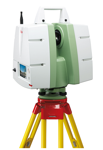
Broad Specifications

  • 50,000 Data Points Collected per second.
  • Range 300 yards
  • 360 Degree Color Photography
  • Able to  produce ¼ inch accuracy
  • Fly through Videos
  • Extremely effective at capturing the scene

Leica C 10 3D Laser Scanner

The technology was invented about 15 years ago to map very precise structures like oil refineries.  Originally it could only be used by trained scientists.  However, in about 2000 the technology became much more user friendly, and by 2005, with the addition of an onboard color camera and compact platform, it quickly became state of the art.  Now in 2011 it is becoming a very effective working tool for capturing existing conditions in any environment.  Now it is use in thousands of different types of data capture task all over the world.

How does it operate? You turn the scanner on and it captures a 360 degree spherical photograph of the area. When the photographic collection is complete the scanner fires a laser at a rate of 50,000 times per second at an effective distance of 150 yards in all directions of the sphere. The laser beam travels out, hits an object and returns the position and elevation of the object and that is one point. The results of collecting millions of these points builds a 3D image that looks like a “hologram” and is called a point cloud. The points are registered to the color photography and are painted with the same color as the pixels in the digital photography and so the points collected  are colored and measurable to an accuracy of about ¼ of an inch. All the data is graphic and represents  the most precise way that you can capture data.  We have been using this technology at LandAir Surveying for the last 7 years which has allowed us to become very proficient with the many tools it provides.

What tools does it give you that you do not have?

  • You have 360 degree photographs of the scene, and you can walk a jury down the road or inside a house and let them look at everything in every room in color from any view.
  • You can overlay the scan data over the photographic data and make precise measurements between any two points real time while testifying.
  • You can place a virtual camera anywhere within the 3D scan data and view the scene from infinite points of view.
  • You can build a fly through video and take the jury down the road at any speed you choose.  For Example, you can show the scene in slow motion and then speed up the camera to actual speed showing a car traveling at 40mph per hour, thus demonstrating what the driver saw and viewed at that speed. You can then show the same scene in slow motion so a jury can study the details.
  • Inside a house you can show a room or scene from any view and show the jury what a homeowner would see looking out of their window and what a person outside would see looking in from the street, and everything would be geometrically perfect.
  • The information collected can be used to build a re-creation of an accident or crime and can show your version of how the crime or accident most likely occurred.

All of this is done with photography and scanned points that are registered together and which are scientifically calibrated and precise.  These tools are very powerful communication tools and judges like them because they save the jury trips to the site.  Police departments all over America are now starting to use this method to document their crime scenes and present their evidence of a crime.  They are able to use the information collected to show line of site details and what perpetrators and victims saw from different points of view.  If new evidence comes up a year later they can make new measurements from the original data.

How much does it cost?

Most jobs consist of field data collection and a good scanning group should be able to get 8 to 10 set ups per day with a long range scanner which includes the 360 degree spherical photographs. The data is then processed and a video for the client is made.  For example driving down the center of the road at some speed, and the ability to view and manipulate the photographs on the provided FREE software call “TrueView”.

This basic package can cost from $3500 for a relatively small site and of course the cost goes up as the size and the complexity of the project increases.  This is sufficient to take into court.  Smaller jobs may include scanning four ways down a busy intersection.  Anyone can use the software provided to run the Windows Media files and open and view the 360 degree photos. In complicated cases we also can build accident recreation videos showing the accident as we believe it happened based on the facts this takes more time and cost more.

When the bus accident occurred on I 75 and Northside Drive in Atlanta the scene was scanned to collect data.  When the bridge collapsed in Minneapolis the scene was scanned.  When Princess Diana died in a car accident in a tunnel in Europe that became to most scanned accident scene in the world.

There are many more uses of the data depending on what a legal team needs in order to show their version of the incident.  For example, we can create multiple views of the same situation to show what somebody may or may not have been able to view of an incident based on where they were standing. We can create camera views at eye level in a car or at eye level of a bystander standing next to a pole.  We can insert realistic car models into a video and show the view from the windshield looking out.  We can show the same car as viewed from the top of an overpass as it drives under the overpass.  All this comes from the original data collection.

What steps are necessary to use the information and make a presentation in court?  Below are the actual preparation and steps for one of our recent court cases.

This case involved working with a criminal defense team to help defend Joe Client.  He was charged with vehicular homicide and the case had been moving through the system for 5 years.

Step 1. We met with the defendant and all the defense attorneys and walked the site to determine what was important to them.  We discussed all the facts and looked at what little evidence remained at the scene.  We listened to our client tell his version of the incident. Our task was to clearly document the site to show the court.
Step 2. We reviewed the photographs that were 5 years old and begin to study the evidence. We were provided police reports, photographs and other pertinent information regarding the case.
Step 3. We discussed with the defense attorney the area to be scanned for the presentation.
Step 4. We collected the scan data and 360 degree photographs of the site.  This took about a 2 days.
Step 5. With our processed data and photographs we met with the defense team and presented several site videos of the travel of the car as it had been described.  We determined that we would produce one video example in slow motion for detailed study of the scene and a second at real time speed.
Step 6. We began to build sequence boards that would be the basis for the design work of the accident re-creation video presentation.  We used the photographs, the evidence, the police reports and the scan data to build the information needed.
Step 7. We produced our first animation in black in white and delivered it to the defense team for their input.  The team was very impressed and enthusiastic and immediately started giving us input and making great suggestions.
Step 8. We produced a second version and then a final version of the re-creation that we would present in court.  We were convinced that we had made the re-creation as close as possible to the police reports and to our client’s account of the accident.
Step 9. We presented the final version to a mock jury.  They are obviously taken with the realism of the animation and immediately understood what took place .  They voted for acquittal.  We used their input to make a final adjustments to the video recreation.
Step 10. We went to court and were prepared to show the court how the technology works, show the digital video fly through, the 360 photos showing the accident scene and finally the accident re-creation.  During pretrial motions we were told to go in the empty jury room where we presented all our information to the prosecutor with the defense team and we were question at length by the prosecutor as to the technology and the data collection process.  The case was  settled on a plea later.

Conclusion

3D Laser Surveying is now starting to become a forceful forensic technology that can be used to bring data to court cases that was not available even 5 years ago.  This is the most advanced way to collect crime scene and civil accident data and has been used in many courts across the country.  This method is currently being used in all types of civil and criminal litigation including civil cases and insurance case where a catastrophic even or arson has taken place to bring the scene to the courtroom and show them scientifically, graphically and intuitively what the environment in which a civil or criminal incident looked like, and it allows for permanent 3D archival of the area involved.

H. Tate Jones Ga. RLS
Contact information tjones@lasurveying.com
1875 Old Alabama Road Suite 1120 Roswell, Ga
770 730 9950

Appendix A

Court and Forensic References

(Norcross, Ga., 03 September 2009)  District Attorney Joe Mulholland of the South Georgia Judicial Circuit added yet another legal case reference to the growing number of U.S. court cases in which Leica Geosystems 3D laser scan data has been admitted into evidence when he successfully proffered and tendered to the jury a visually compelling Leica TruView.

During the murder trial of Antonio Jerome Greenlee in Decatur County Superior Court, witness and crime scene investigator, Andy Forte of the Thomas County Sheriff’s Department, used Leica TruView to virtually place the jury at the crime scene and to show them how the homicide could have occurred.  The case stems from the homicide of 21-year-old Ebony Clarke of Bainbridge, GA, who was shot and killed on August 12th, 2008, during a street altercation between two men.

Leica TruView is a free, web-enabled panoramic point cloud viewer that allows users to view, pan, zoom, measure and markup the incredibly rich point cloud captured by the Leica ScanStation 3D laser scanner.  The Leica ScanStation allows investigators to first photograph and then make millions of measurements of a crime scene in just a few minutes thus “freezing the scene in time” forever.  A Leica TruView data set can then be generated in minutes after scanning for briefings or analysis or as in this case as a jury exhibit.

“The jury really, really liked it and we had jurors comment afterwards about how effective it was” said District Attorney Mulholland.  “We not only used the TruView to support Andy’s testimony, but the judge then allowed Andy to show it again during my direct examination of other witnesses as I asked them questions about where they were standing or where the shooter was.  TruView is basically a high-tech picture.  It is not testimony.  It is offered as an exhibit and demonstrative evidence.  This seemed to play well with the judge.  The Defense did not object and I think that they thought the same thing.”

Mulholland went on to say that after the trial the judge called him to the bench and commented on how effective the use of the Leica TruView was and encouraged him to use it again.  “We certainly plan on doing so.  The scanning software was absolutely fantastic” said the D.A. The judge also contacted Thomas County Sheriff R. Carlton Powell to thank him for his agency’s assistance with the case and to compliment him on the professional nature of the exhibits generated by his investigators.   Sheriff Powell was instrumental in bringing ScanStation technology to Georgia law enforcement and has made it available to the Georgia Bureau of Investigation and other agencies as a courtesy.

  • California DOJ Invests in 3-D Crime-Scene Laser Scanners to Support Forensic Crime Scene InvestigationAfter seeing first-hand how the Leica Geosystems ScanStation 2 can be deployed to quickly measure and model extensive indoor and outdoor mass casualty mock crime scenes, the California Department of Justice’s Bureau of Forensic Services (BFS) moved quickly to purchase two Leica ScanStation 2 high speed, high definition 3D laser scanning systems from Leica Geosystems.
  • Pennsylvania State Police Response to Amish School Shooting
  • The Amish School shooting occurred on the morning of Monday, October 2, 2006 when a gunman took hostages and eventually killed five girls (aged 7–13) and then killed himself at West Nickel Mines School. The Pennsylvania State Police used a Leica laser scanner at the scene for forensic mapping.
  • Albuquerque Police Chief Ray Schultz discusses the reasons his department acquired a Leica ScanStation for crime scene investigation.
  • This BBC news clip shows British Police Investigators in the Paris tunnel where Princess Diana died using a Leica 3D laser scanner.
  • 3D Scanning: Laser Scanning the I-35W Bridge Collapse
    Professional Surveyor Magazine – March 2008
    Bruce Jenkins
    Much has been made of the role aerial mappers and surveyors have played in victim rescue and bridge reconstruction after the August 1, 2007 collapse of the I-35W bridge in Minneapolis. But what about laser scanning? This is the story of how the Minnesota Department of Transportation deployed 3D laser scanning to capture a detailed forensic record of the bridge collapse and help with the ensuing investigation.

Taking a Chance with Laser Scanning Technology

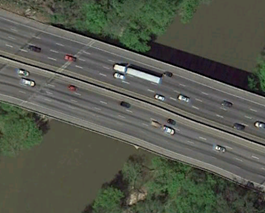
LandAir Surveying began doing business in the 1988 by offering site and topographic surveys to the engineering and construction industry. The company originally started with two survey crews. There were fewer than ten employees and surveying services were offered in Georgia and nearby states. Over the next ten years the business expanded tremendously to include cell tower site surveying services to telecommunications providers. Three-thousand or more cell tower sites were surveyed with conventional survey methods. In 2002 there was a shift of focus to transportation engineering projects and in 2005 we got a project to survey the I-20 Bridge over a large river near Atlanta, Georgia. It was this shift that transformed the technology used and overall business direction of LandAir Surveying. Problems arose with the traditional surveying methods. The size and length of the bridge made it difficult for a survey team to get an accurate survey with the traditional survey equipment. Our owner sought alternative solutions and in the process determined that 3D laser scanning could be used to achieve more reliable results for the bridge survey.

Adjusting to 3D Laser Scanning

LandAir Surveying purchased their first laser scanning equipment in 2005 after viewing demonstrations and since then have expanded into newer and more specific and advanced models. The scanners were used in conjunction with more traditional surveying methods. Work flow methods were refined as experience grew with the new technology. With this increased experience 
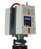
came calls for exterior, interior, and structural surveys of various buildings and environments. 3D laser scanning made it possible to easily scan a building and produce drawings and 3D data sets based on the scan. Time required to produce an accurate survey was reduced with the help of this technology. Enhanced scanning allows surveying of building areas that are not easily accessible without the technology. Larger jobs such as wide spread manufacturing facilities have more accurate site surveys with complete 3D imaging and laser scanning is becoming more of a standard in these  environments. These types of surveys would not be possible with traditional surveying methods. Data processing had to be refined to better handle bigger data sets created by laser scanning. New scanning innovations have created safer work environments for surveying crews and new business opportunities.

3D laser scanning is quite different from other surveying methods. With this technology, field notes do not exist. Instead, surveyors strictly deal with data points and image files. A typical 3D laser survey project work flow is to set up the equipment and seek a line of sight for each point. Scanning devices use technology that floods a area with precise data points at rates of up to 300,000 points per second. After a scan is complete, the information can be viewed, verified, and referenced whenever necessary. Files are large in size and have to have the right computer power and resources for proper management. Machines with vast amounts of RAM and enhanced graphic cards make critical post-processing more reliable. These computers must be capable of supporting vital processes such as proper data workflow, storage, retrieval, and backups. While the service is advantageous, we found that more effort is required to find clients who can benefit from the technology. Initially clients could see the benefits, but not all could afford the service. However as the technology grew and became more efficient and the benefits became more reliably more companies are using this technology as a way of surveying existing conditions.  Having been in the 3d Laser Scanning business for 7 years our firm has become an industry leader in this emerging technology.

Our first choice provider for Mapping and Surveying

I would  like to thank you for the work you and your firm have done with Parsons Brinckerhoff   by  providing  Aerial  Mapping  and  Land  Surveying  services.  You continue  to be our first choice  provider  for Mapping  and Surveying  professional  services.   You have set the standard  which  we expect  from  our subs.   Your cooperation   and teamwork  is complimented   with your responsiveness   and  professionalism.     You have established   a solid  reputation  with GDOT our ultimate  client  as well as our Project  Managers  here at PB on both the Noise Walls on 1-85 project  in Coweta  County  and the  Noise Walls on 1- 285 in DeKalb  County  On both these  projects,  you once  again  proved  to be  accurate  with your work, ahead  of schedule  on your deliverables   and within  budget.
It is without  hesitation  that  I would  consider  using  LandAir  on future  projects,  and would recommend   your firm to others.

Sincerely
PARSONS BRINCKERHOFF
Senior VP

What can you do with a 3d Laser Scanner

What can you do with a 3d Laser Scanner that you cannot do with other types of surveying and mapping equipment?

Scanner on 5” standard Tri Pod

Scanner on 5” standard Tri Pod

First let’s look back at where the 3D Laser Scanner came from.  Some people call it a Laser Scanner; Aerial mappers call it tripod scanning. I think it is more widely known as terrestrial scanning.  So laser scanning as I am talking about is all done on a tripod that is anywhere from 5’ tall to 15’ tall.  Most are moved around either on wheels attached to the tripod or by hand or now we even have truck mounts to improve speed.  As I said in my first article the uses’ for this technology are as varied as the imagination.  So what do they do that other survey and photographic equipment does not do.  Let’s look at what they do very well.  They collect very precise points in space and a very high rate of speed and the photography gives the laser  the ability to color these points.  This seems like a simple thing and one could wonder why it is such a big break through.  Because these points are precise one is able to go scan and object and then reproduce that same object in a computer.  Not only reproduce the dots but reproduce almost every feature that comprises that object.

3DLaser Scanner being mounted on a 15’ tripod

3DLaser Scanner being mounted on a 15’ tripod

In 2005 the movie “Troy” was being produced and the need for a very good replica of the Parthenon needed to be built on set in Hollywood California.  You could imagine the amount of work it would have taken to get hundreds of people with measuring devices to go and measure the real Parthenon and then draw up the plans.  This was a perfect job to do with the new 3D Laser Scanning technology.  The movie company hired a scanning company to go over to Italy and make a very thorough series of scans.  From these scans which were accurate with in a ¼ of an inch detailed plans were drawn up and the replica with constructed from the plans produced by the scanner.  The point here is that this is the perfect instrument to completely and thoroughly map existing conditions.  That is one of the strongest features this computer/machine produces.  The first scanners came from LIDAR technology.

LIDAR (Light Detection And Ranging) is an optical remote sensing technology that measures properties of scattered light to find range and/or other information of a distant target. The prevalent method to determine distance to an object or surface is to use laser pulses. Like the similar radar   technology, which uses radio waves, the range to an object is determined by measuring the time delay between transmission of a pulse and detection of the reflected signal. (source wikipedia).

The first uses of this technology were in aircraft mapping the earth surface.  The rapid fire laser technology would send out a light beam at a high speed using a very powerful laser and it would hit the earth and create a point.  With millions and millions of these points  created from the laser pulses a very accurate map of the earth surfaced was generated.  A gentleman named Ben Kacyra understood the technology and with the help of his partners and funding invented the first terrestrial 3D Laser scanner.  His reasoning was that he worked in the piping industry and he was looking for a better way to map complex piping runs in refineries and heavy industrial complexes.  The technology worked well and from there on was expanded in to the more sophisticated scanners we have today.

So the best feature of the scanner is that it can precisely map existing conditions and this ability has been translated into many fields.  A whole new field of 3D engineering has evolved around this technology.  Our first use of the technology was in existing road surveys for the Department of Transportation. LandAir Surveying has a long history of working with the Georgia department of Transportation.  We were surveying a very long bridge over Atlanta’s biggest river and we were having a very difficult time capturing all the existing bridge structure using single point total station survey technology and meeting the specifications.  As an experiment we tried the same work with a 3d Laser Scanner and we captured all the information we needed with little difficulty.  That was our first project and since 2005 we now have completed hundreds of projects.


Color scale show change in elevations’ in this 100 year old farm house.  In  a 3D Laser scan

Some of our more memorable projects included:

Providing our client with a floor as built of a building that was approximately 500,000 square feet.  The client was a contractor and they needed it for their client to determine that the floor met the specification for being level.  In two days we scanned and captured about 10,000,000 points.  Then we presented the data to the client firms in colored contours that we 1/8th inch contours and every time it changed by another 1/8 inch the color also changed.  Ultimately we provided them a 10 foot grid and the floor did meet the specification.

We have surveyed structural walls that were either settling  or sinking and we survey the amount of settlement over a period of time and showed graphically and with excel spread sheet how much movement we detected.

We have surveyed mines both above ground and below and underground and were able to give the client a map of the existing conditions.  In doing this we also were able to keep our crews safer and they did not have to go into the working faces of the mines which can be very dangerous.  Because of the range the laser collects data we were not with in what the miners call the “working face” area which is much more susceptible to falling rock and surrounded by large heavy moving equipment.

As we go forward in this publication we will talk more and more about the different types of projects we have worked on and how the scanner was used to collect information that otherwise could not be collected.

3D Laser Scanning revolutionizing data collection

3D Laser Scanning technology is currently revolutionizing data collection in every phase of engineering architecture planning manufacturing and design and fabrication.

“…3D Laser Scanning will have an impact on the design and engineering world equal to the digital calculator or GPS technology…”      H Tate Jones 2005

That statement is truer now than it was then.  The technology is not only affecting the design and engineering world it is starting to be used in ways to span the imagination.  There are multiple types of scanners and they range from scanners that literally map the globe on a regular basis, mounted to the space shuttle, to scanners that map your brain and are used by surgeons.  Believe it or not the data format is basically the same from all these different types of scanners.

What is the technology?

Z&F Phased based 3D Laser Scanner

Z&F Phased based 3D Laser Scanner

3D laser scanning is a process involving the use of high speed lasers that fire at incredibly high rates of speed.  There are two different types of scanners that are commonly used in 3D laser scanning in the context that I am writing aboutPhase Based and Time of Flight. Phased base means that a constant beam of laser energy is emitted from the scanner and the change of phase of the laser light is measure to allow the scanner to calculate a distance.  The advantage of this is higher point capture.  Currently up to 2,000,000 points per second.  The down side of this is much shorter range, currently about 30 meters.

Leica ScanStation II Time of Flight 3D Laser Scanner

Leica ScanStation II Time of Flight 3D Laser Scanner

In a time of flight scanner a pulse of light is emitted from the scanner. The time it takes for the pulse to travel from the scanner to the object and back is measured allowing the scanner to calculate the distance. The key benefit to this type of scanner is longer range scanning. The down side of this type is that they do not collect as many points.  Currently they collect about up to 50,000 points per second.  For the reasons above the phase based technology is used inside more often and the time of flight is use outside more often. However best practice is that you used both inside and outside as necessary to get a very precise and accurate scan.

Both of these methods produce millions and sometimes billions of individual points.  The points are located in space geometrically and have a very precise relationship to each other.  As you can imagine this creates a very dense point group.  These millions of points create a geometric hologram currently called a “Point Cloud”.  The point cloud is a very exact replication of the 3D environment in the effective area around the scanner.  So if the scanner is placed inside a building the interior is of that building is shown in great detail.  So detailed that precise measurements can be made of the physical geometry of the surroundings.  This points can be used to capture such irregular surfaces as the interior of an automotive plant with all the cables wires beams and moving parts that are contained in that environment.  These point clouds can measure the buildup of snow on the side of a mountain.  They can measure and represents roads, bridges, historic architecture, streets, towers, trees and millions of more examples. They can also measure very small microscopic items like the inside of a watch or very fine machined parts.

In order to be clear of the terms that are used in this field, below are some common terms that are used in the 3D Laser Scanning field:

Common Laser Scanning Terms:

Point Cloud Millions of points geometrically connected in space which are measurable.

Mesh Small triangles used to make a surface that can be read by a computer.

Modelling Building Cad models inside computer programs that represent building parts and   can be measured and manufactured and tested.

Change Detection Making repeated measurements of the same surface at different times that can detect movement on a surface in the surface.

Clash Detection Comparing design models to other design models or point clouds.

Spherical Photography Photography that can be view in 360 degrees.

Noise Points around a scan that are not the surface of the object but are reflected off the  object.  These can be cleaned and removed from the scan data if necessary.

Traversing Moving a scanner from one point to another and keeping up with the geometry   between points to establish the exact position of the 3D Scanner in space.

Laser Refraction This is caused by the laser passing through a window or opaque surface.  Can also be caused by water. This must always be considered.